
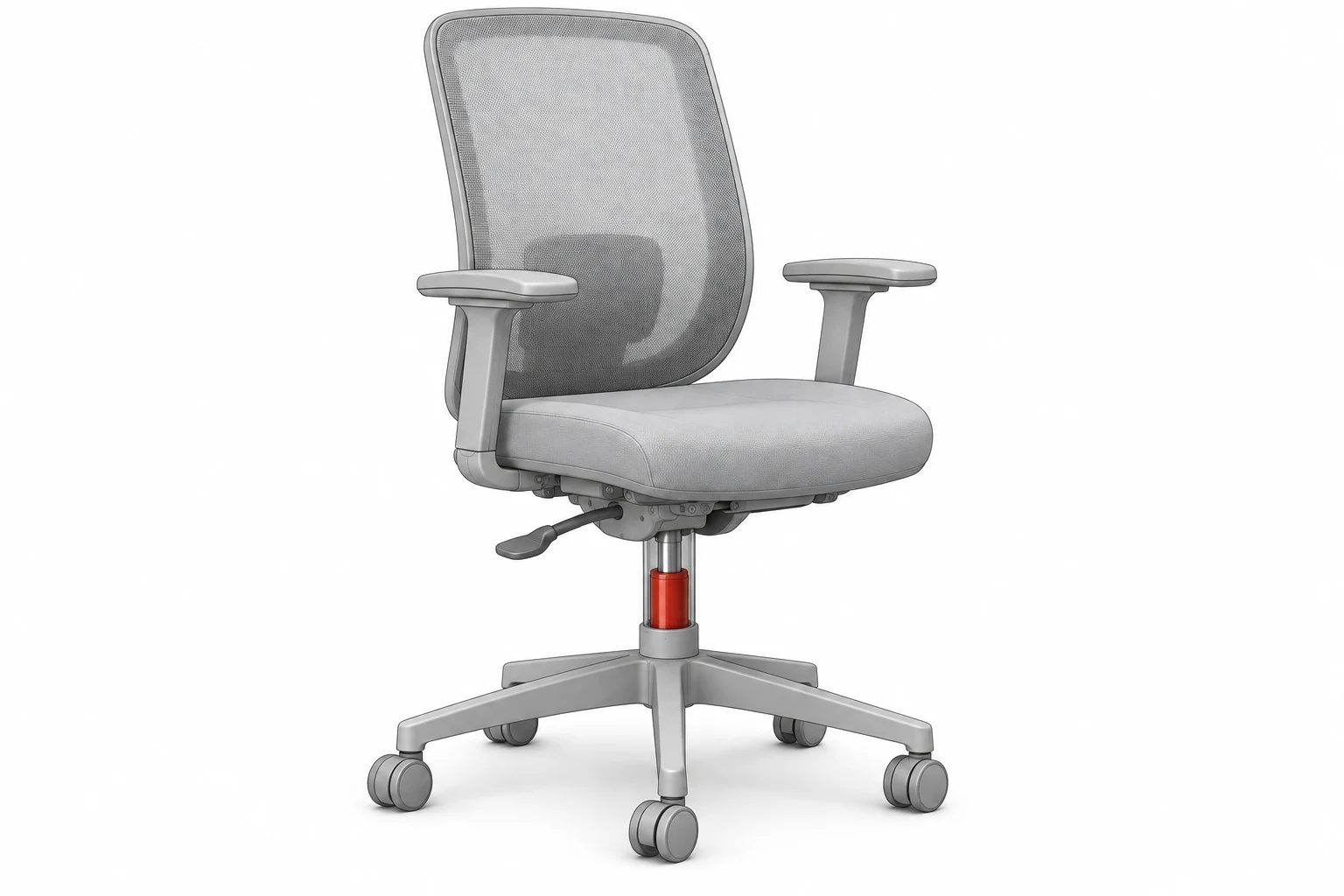
The vertical column connects the base to the seat mechanism.
01View matching guide →
Office & task chairs
Pneumatic height adjustment
What to identify
Extended and compressed heights; upper/lower tapers; release arrangement
Chair-height gas lift columns and separate lockable backrest supports for seating manufacturers and parts distributors. Choose the component by its adjustment function, then compare the relevant dimensions and interfaces.
The vertical column connects the base to the seat mechanism.
Pneumatic height adjustment
Extended and compressed heights; upper/lower tapers; release arrangement
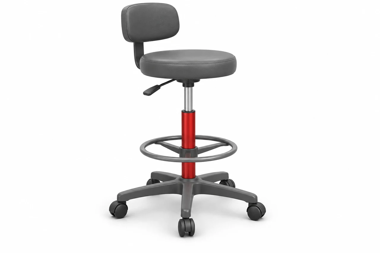
A dedicated gas-lift column adjusts seat height.
Height adjustment for seating assemblies
Required height range; column dimensions; release position
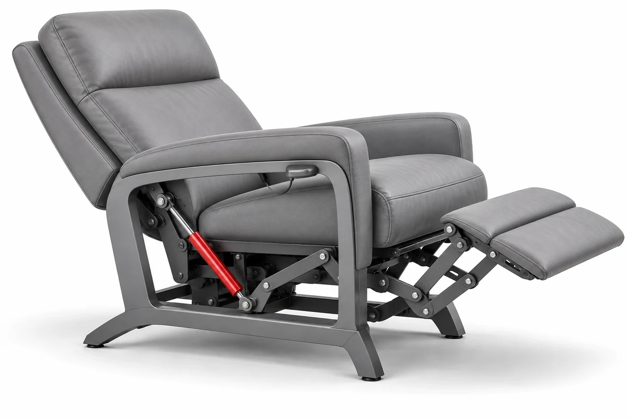
A separate locking support acts on the backrest linkage.
Gas-spring-assisted seating adjustment
Lockable gas spring specification; cable/lever; brackets
Application concepts show example mechanisms and gas spring locations. Use your installed part, dimensions and connections to define the final fit.
A chair gas lift connects the seat mechanism and base through dedicated interfaces. A separate lockable gas spring may control a backrest or leg section. Match the relevant component and release control, rather than choosing by chair appearance.
Third-party brand names and part numbers are shown for cross-reference only. Send the reference and quantity; we quote gas springs made in our own factory and confirm the dimensions and connections in your quotation.
A chair gas lift sets the seat height of a swivel chair or stool. It is matched by its extended and compressed heights, its seat and base tapers and its release arrangement; sizes and options are on our office chair gas cylinders page. Two of the 12 published column references:
Match full column, taper position, seat/base interfaces and release mechanism; stroke differs from the published seat adjustment range.
Complete chair gas-lift column
Drawing length L: 395.5 mm / 15.57 in
Stroke: 132.5 mm / 5.22 in
Spring extension force: 350 N / ≈78.7 lbf
Column drawing length L, not eye-to-eye strut length
Chair seat/base taper interfaces; taper position C is part-specific
Taper position C: 94 mm / 3.70 in; Standpipe length B: 220 mm / 8.66 in; Seat adjustment range: 120 mm / 4.72 in; Outer tube diameter: 50 mm / 1.97 in; Pressure tube diameter: 28 mm / 1.10 in; Drawing dimension A: 169–301.5 mm / 6.65–11.87 in
Spring extension force is not an occupant weight rating.
Match full column, taper position, seat/base interfaces and release mechanism; stroke differs from the published seat adjustment range.
Complete chair gas-lift column
Drawing length L: 354.5 mm / 13.96 in
Stroke: 111.5 mm / 4.39 in
Spring extension force: 350 N / ≈78.7 lbf
Column drawing length L, not eye-to-eye strut length
Chair seat/base taper interfaces; taper position C is part-specific
Taper position C: 110 mm / 4.33 in; Standpipe length B: 200 mm / 7.87 in; Seat adjustment range: 100 mm / 3.94 in; Outer tube diameter: 50 mm / 1.97 in; Pressure tube diameter: 28 mm / 1.10 in; Drawing dimension A: 133–244.5 mm / 5.24–9.63 in
Spring extension force is not an occupant weight rating.
See all 12 chair gas lift column references →
A separate lockable gas spring holds a backrest, armrest or leg section in position and is released by a release head, cable or lever. The 20 published EL1 and EL2 elastic-locking references run from 20 mm to 250 mm stroke; here is the same 60 mm stroke in both versions:
Backrest and armrest adjustment reference. Select the force, end fittings and release system, then match the exact seating mechanism and mounting geometry.
Drawing length L: 190 mm / 7.48 in
Compressed: 130 mm / 5.12 in
Stroke: 60 mm / 2.36 in
Selectable force: 200–800 N / 45.0–179.8 lbf
Force selection and mounting interfaces are confirmed for the quoted assembly.
Tube / rod diameter: 22 / 10 mm
Manufacturer's standard-range drawing (extended / compressed length); confirm final mounting centers with the selected fittings
Tube-side attachment and rod-side release head selected separately
Force selection increments: 50 N / 11.2 lbf.
Backrest and armrest adjustment reference. Select the force, end fittings and release system, then match the exact seating mechanism and mounting geometry.
Drawing length L: 190 mm / 7.48 in
Compressed: 130 mm / 5.12 in
Stroke: 60 mm / 2.36 in
Selectable force: 200–1000 N / 45.0–224.8 lbf
Force selection and mounting interfaces are confirmed for the quoted assembly.
Tube / rod diameter: 28 / 10 mm
Manufacturer's standard-range drawing (extended / compressed length); confirm final mounting centers with the selected fittings
Tube-side attachment and rod-side release head selected separately
Force selection increments: 50 N / 11.2 lbf.
See all 20 recliner and backrest references →
Explore all reference records →
Match a height column to its own drawing. A separate backrest support has different mounting and control dimensions.
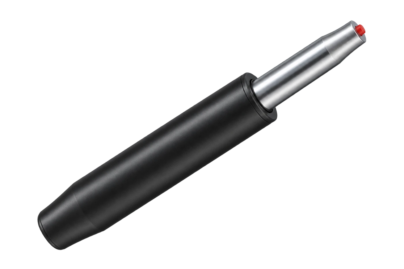
Complete chair-height columns and internal cylinders, ordered by their own interface drawings.
Explore the range →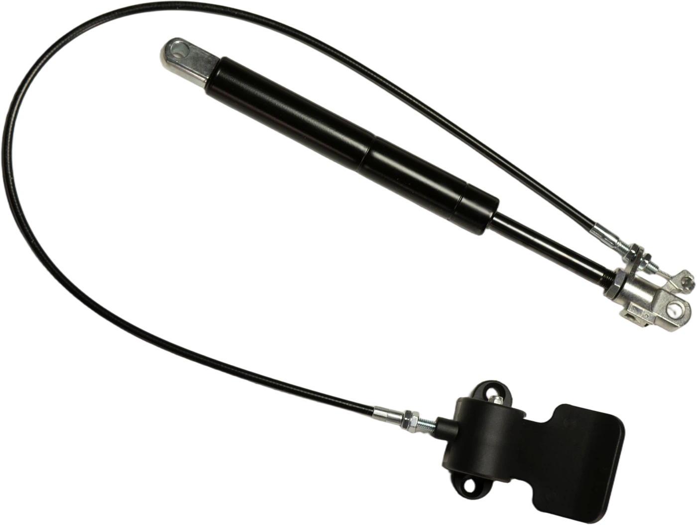
Separate lockable backrest springs with selected release heads, cables and levers.
Explore the range →Send the reference and quantity for each item. We will match the requirement and prepare a quotation for your order.