
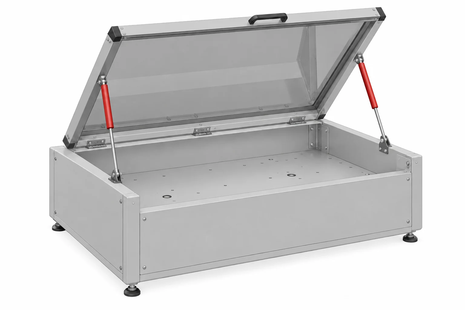
Fixed machine enclosure to the hinged service cover.
01
Machine covers & guards
Inspection panels, protective hoods and service covers
What to identify
Original part; cover travel; lengths; force and connections
Gas springs for equipment covers, guards and access panels, with locking options for adjustable supports. Match the existing part or provide a drawing with mounting details.
Fixed machine enclosure to the hinged service cover.
Inspection panels, protective hoods and service covers
Original part; cover travel; lengths; force and connections
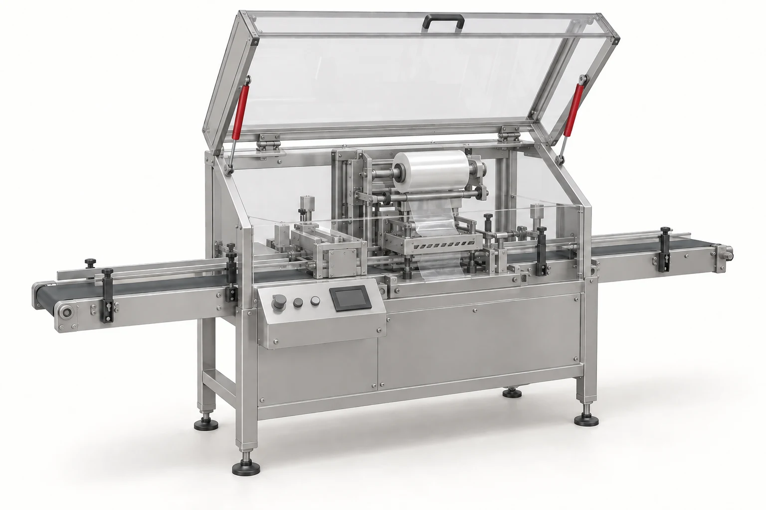
Fixed machine frame to the raised protective hood.
Equipment lids and maintenance access. For washdown areas, see stainless gas springs for food machinery.
Cover function; cleaning exposure; dimensions; material requirements
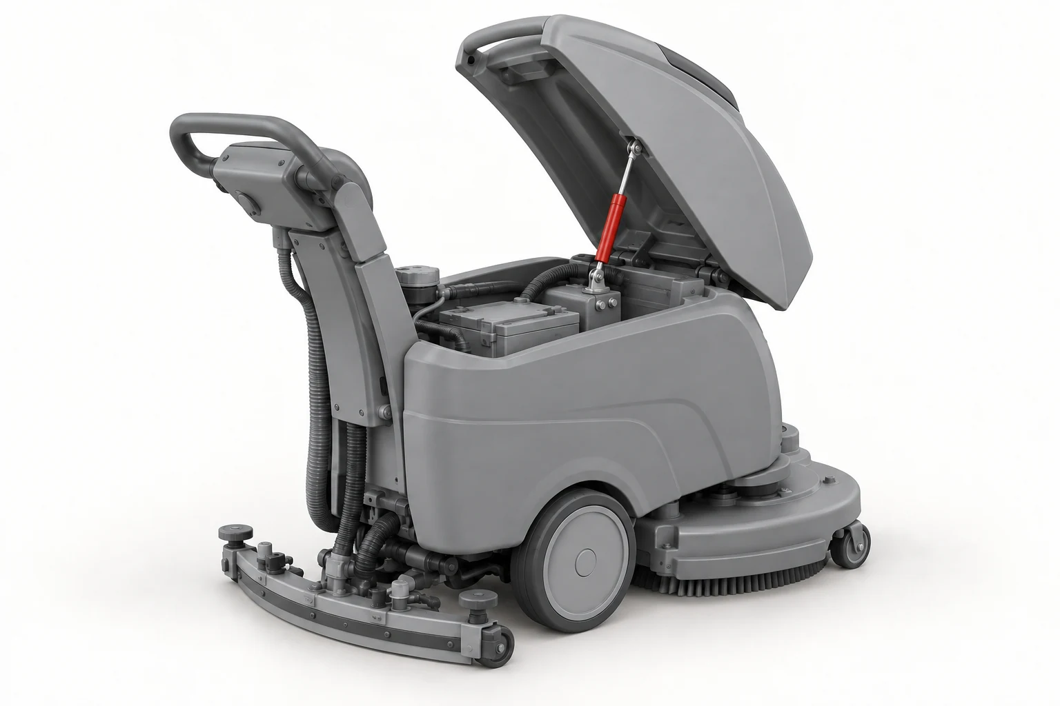
Fixed chassis bracket to the raised maintenance cover.
Hoods, lids and service panels
Operating environment; original marking; both ends
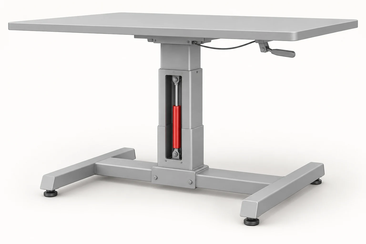
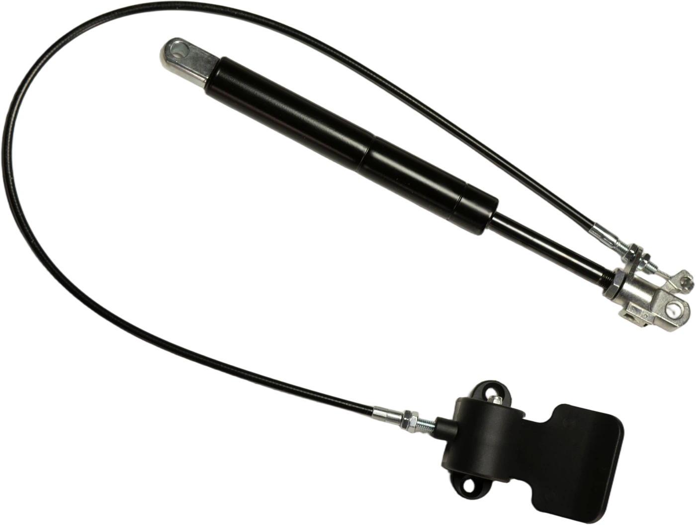
A release-controlled spring works inside the guided column; housing is opened for illustration.
Gas-assisted work surfaces and adjustable operator supports
Locking behavior; travel; control/release method
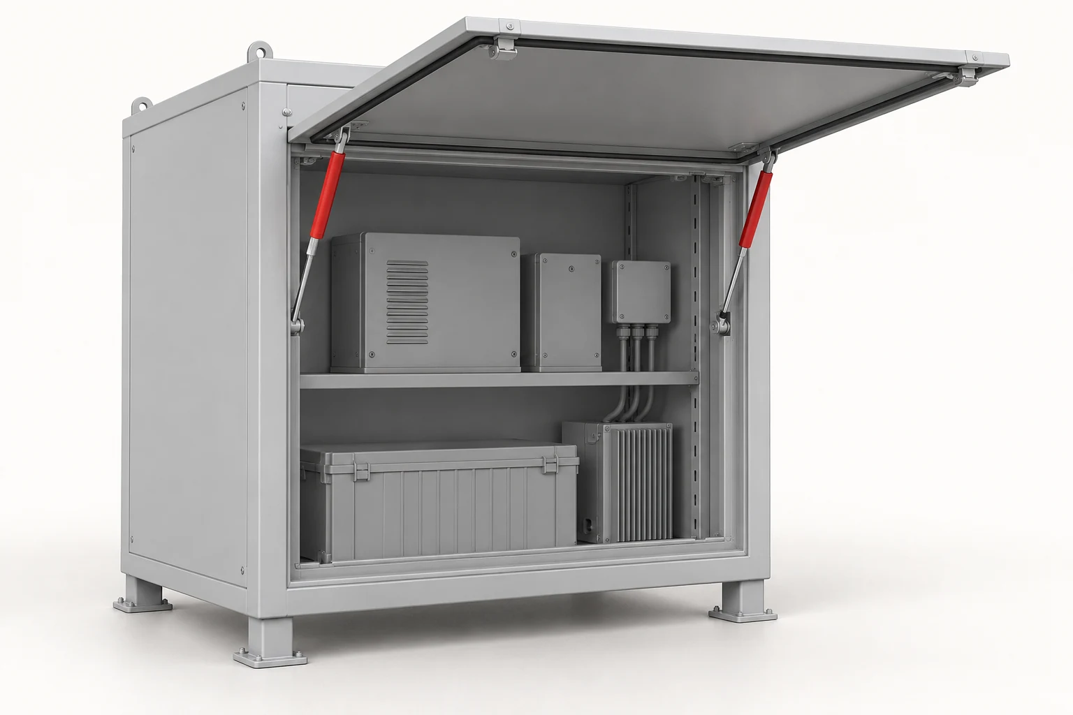
Fixed cabinet side to the top-hinged access panel.
Access flaps and service openings
Panel opening direction; mounting space; connection dimensions
Application concepts show example mechanisms and gas spring locations. Use your installed part, dimensions and connections to define the final fit.
Machine guards and inspection covers usually need controlled opening and support. Adjustable tables and control panels can require position locking. Capture the fitted unit, mounting clearance, force and working environment with the equipment reference.
Third-party brand names and part numbers are shown for cross-reference only. Send the reference and quantity; we quote gas springs made in our own factory and confirm the dimensions and connections in your quotation.
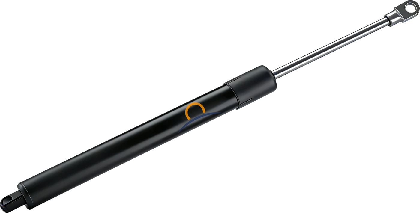
Reference size with a selectable force; compare the clevis interface.
Drawing length L: 224 ±2 mm / 8.82 in (nominal)
Stroke: 80 mm / 3.15 in
Selectable force: 50–420 N / 11.2–94.4 lbf
Published type 16-1 selectable force range; force must be specified for the requested part.
Tube / rod diameter: 15 / 6 mm
Technical reference: 16-1-111-90-A17-B17
Published dimension L in manufacturer's drawing
Welded clevis / clevis
Reference size with a selectable force; compare the clevis interface.
Drawing length L: 264 ±2 mm / 10.39 in (nominal)
Stroke: 100 mm / 3.94 in
Selectable force: 50–420 N / 11.2–94.4 lbf
Published type 16-1 selectable force range; force must be specified for the requested part.
Tube / rod diameter: 15 / 6 mm
Technical reference: 16-1-131-110-A17-B17
Published dimension L in manufacturer's drawing
Welded clevis / clevis
Reference size with a selectable force; compare the clevis interface.
Drawing length L: 366 ±2 mm / 14.41 in (nominal)
Stroke: 150 mm / 5.91 in
Selectable force: 50–420 N / 11.2–94.4 lbf
Published type 16-1 selectable force range; force must be specified for the requested part.
Tube / rod diameter: 15 / 6 mm
Technical reference: 16-1-189-154-A17-B17
Published dimension L in manufacturer's drawing
Welded clevis / clevis
Need another reference? Send the complete marking, photos and quantity →

Send the reference and quantity for each item. We will match the requirement and prepare a quotation for your order.